Solar Fan Controller - SOLFACON
Configuration tool & build instructions
Please read through the whole page before you start assembling the controller. If you for instance plan on mounting the controller in an enclosure, there are some considerations to be taken before choosing your components and assembling the PCB. Selecting or deselecting features will also update the instructions accordingly.Select features
| An on/off switch to turn the controller on and off. | ||
| Protect the controller from damage from reverse polarity, e.g. if the positive and negative leads of the solar panel are switched by mistake. Increases the power consumption a little. | ||
| A dial to set a stable maximum fan speed, to reduce noise or power consumption when/if needed. Without this the fan always run at the maximum possible speed. Only works with 4-pin fans. | ||
| Lets the fan operate periodically even when there is not direct sunlight, and effectively assists with starting the fan up in low/medium light scenarios. | ||
| An extra fan header to connect a second fan to the fan controller. Alternatively daisy chaining is also possible. |
Components
You can choose to use alternative components to the ones listed here, for instance if you have similar parts available. Pay attention to the width and pitch dimensions of the components - and especially the height if you plan to mount the PCB in an F19 enclosure.| ID | Type | Value | Model | Notes |
|---|---|---|---|---|
| C-ALT | Electrolytic capacitor | 2200uF | ELZA350ELL222MM20S | Only applicable when not opting for low power operation. |
| C1 | Electrolytic capacitor | 390uF | RF1V391MP30820E | Voltage rating should be higher than the open circuit voltage of the solar panel with some margin. For a 22V solar panel, use 35V or above. Note that low temperatures can increase the open circuit voltage substantially. |
| C2, C6 | Ceramic capacitor | 1uF | FK24X7R1H105KR000 | Voltage rating should be higher than the open circuit voltage of the solar panel. For a 22V solar panel, use 35V or above. |
| C3 | Tantalum capacitor | 15uF | TAP156K025SRW | Voltage regulators are often sensitive to the ESR ratings of capacitors, so replacements should take this into consideration. |
| C4, C10, C11, C12 | Ceramic capacitor | 0.1uF | FG18X7R1H104KNT06 | Standard decoupling capacitors. |
| C5 | Electrolytic capacitor | 100uF | ER1C101MP26307RU | Some voltage regulators are sensitive to large output capacitance, so replacements should take this into consideration. |
| C7, C8 | Super capacitor | 1F | CZP-8R1L105R-TW | The PCB is compatible with super capacitors with 13.5mm and 20.5mm pitch. These two capacitors MUST be identical, or stability and durability can easily be compromised. Replacements should consider the following: physical size (width, depth, and height), unbalanced voltage rating (as these will be in an unbalanced configuration), maximum peak and endurance current (experienced during charging and discharging). Smaller capacitors tend to be rated for less current, but can be a more economical option for single fan use. |
| C9 | Tantalum capacitor | 4.7uF | TAP475M016SRS | Replacements should consider the capacitor requirements of LDO3, particularly ESR. |
| D1 | Diode | 1N5408 | 1N5408 | Reverse polarity protection diode. |
| D2, D3 | Diode | - | STPS3L60Q | Replacing these diodes requires some consideration. D2: The forward voltage drop should be small, or the body diode of Q1 will not let LDO1 supply LDO2 (and the MCU) exclusively. D3: The forward voltage drop of D3 should be equal to or slightly higher than D2. It should have low reverse leakage to protect SR1 and to prevent slight charging of the gates of Q1 and Q2. It could be tempting to use SB140 diodes (cheaper, and identical to D4 and D5), but they leak a little too much. |
| D4, D5 | Diode | SB140 | SMC SB140 | Replacements should have a low/moderate leakage current at 12V and low forward voltage. |
| FAN1, FAN2 | Fan header | MOLEX KK254 4x1 male | 0470531000 | Can be replaced by a standard 4x1 2.54mm male header or the fan wires can be soldered directly to the PCB (be careful to connect the fan correctly in this case). |
| LDO1 | Low dropout regulator (LDO) | 12V out | MIC2940A-12WT | Pin compatible with 78xx linear regulators, like for instance BAJ2DD0T. A good old 7812 could be used, but an LDO is recommended. |
| LDO2 | Low dropout regulator (LDO) | 3.3V out | AP7381-33V-A | Supplies power to the MCU, so the requirements are modest. A 5V pin compatible regulator could be used instead, but would increase power consumption a little and require some tweaking of the code that determines the 12V rail voltage. |
| MCU | Microcontroller | ATtiny85 | ATTINY85-20PU | Must be flashed before assembly! Use a socket if you would like to modify/update the firmware later on. ATtiny45 and ATtiny25 can also be used with minor code modifications - The data table containing PWM for a given voltage and target speed would not fit into the flash memory of these chips. You either have to modify the table such that it becomes small enough to fit or remove it entirely. If removed, the max fan speed adjustment feature will not work, but if you do not want that anyway, you may save a few cents on a cheaper MCU. |
| Q1 | P-channel MOSFET | - | TSM480P06CH | Replacements should be rated for minimum 1A at 15V or higher, and the gate to source voltage threshold should be circa -2V to -3V and with a very low Rds(on). |
| Q2 | P-channel MOSFET | - | TP0606 | Replacements should have a relatively low Rds(on) to minimize heat dissipation. |
| Q3 | N-channel MOSFET | - | ZVN3306A | Replacements should have a low input capacitance, the gate to source voltage threshold should be below 3.3V, and must be suitable for accurate PWM at 25 kHz. |
| Q4 | N-channel MOSFET | - | STP55NF06L | Replacements should be rated for minimum 1A at 15V or higher, and the gate to source voltage threshold should be below 3.3V with a very low Rds(on). |
| R1, R5 | Resistor | 22K Ω | MFR-25FRF52-22K | - |
| R2 | Resistor | 82 Ω (2W) | FMP200JR-52-82R | This resistor allows C7 and C8 to charge relatively fast when SR1 is off (and thereby Q2 on). Increase the resistance of this resistor if your C7 and C8 capacitors are rated for less than ~200mA. |
| R3 | Resistor | 200 Ω (1W) | FMP100JR-52-200R | Can be replaced with 150 ohm or higher (1W). This resistor determines how fast C7 and C8 charges when the system is powered by SR1. Charging slower when SR1 is on gives the solar panel a chance to increase its voltage and provide a good overhead for SR1 to take advantage of how solar panel output is often current limited rather than voltage limited. If the panel can sustain 18V 60mA, then SR1 can convert that to 12V 80mA, which is a lot better than 12v 60mA. |
| R4 | Resistor | 150 Ω | MFR-25FRF52-150R | - |
| R6 | Resistor | 1K Ω | MFR-25FRF52-1K | - |
| R7 | Resistor | 47K Ω | MFR-25FRF52-47K | - |
| R8 | Resistor | 91K Ω | MFR-25FRF52-91K | - |
| R9 | Resistor | 15K Ω | MFR-25FRF52-15K | - |
| RV1 | Pin header | 3x1 male 2.54mm pitch | - | Pin header for connecting potentiometer to the PCB. |
| RV1-A | Pin header | 3x1 female 2.54mm pitch | - | Pin header for the wires of the potentiometer. |
| RV1-B | Rotary potentiometer | 50K | P160KNP-0QC15B50K | For max fan speed adjustment. Replacements should consider the clearance if mounted in an F19 enclosure, and the intended operating temperature. |
| POWER | Screw terminal | - | - | For connecting the leads from the solar panel. If you want the cable to enter the enclosure sideways (i.e. with a cable gland), rotate it 180 degrees. |
| S1 | Pin header | 2x1 male 2.54mm pitch | - | Pin header for connecting the toggle switch to the PCB. Instead of a physical switch, these pins can also be used to enable/disable the fan by other means, e.g. with a relay controlled by an automated 'smart' system. |
| S1-A | Pin header | 2x1 female 2.54mm pitch | - | Pin header for the wires of the toggle switch. |
| S1-B | Mini toggle switch | - | BNT11SEBQE | On/Off switch. Potential replacements should consider the clearance if mounted in an F19 enclosure. |
| SR1 | Switching regulator | 12V out | R-78K12 | Power efficient switching regulator. *Could* be omitted, but it would vastly increase the power dissipation in LDO1 and decrease the overall efficiency. |
| Enclosure | F19 enclosure | - | F19 or F19-1 | Comes in grey, beige and black, with opaque or transparent lid, with or without ears for wall mounting, made from either ABS or polycarbonate. You can use another enclosure if you like, as long as it is big enough and you have a way to mount the PCB. |
| PCB | 2 layer PCB | - | - | Use the gerber files to order a PCB via your favourite manufacturer or print your own. |
| Screw | 4 x PCB mounting screws | M3 x 5mm | - | Flat end self tapping screws. M2.6 screws will work, but have a little less grip. Nylon top washers recommended. |
| Wire | Silicone wire | ~30cm 22AWG or better recommended | - | 5 x ~5cm wires to attach RV1-A to RV1-B and S1-A to S1-B. Heat shrink for the exposed ends is recommended. |
| Potentiometer knob | - | 6mm hole | - | Must be compatible with a knurled potentiometer shaft. |
Recommended fan: Arctic P12.
Alternatively another fan optimized for static air pressure. There are fans that can move larger volumes of air, but since ventilation usually involves pushing air through a pipe, perhaps with a grille, filter or insect net attached, air pressure is perhaps the most important parameter.
Recommended solar panel: 20-30W, open circuit voltage of 20-23V.
If you only need one fan and live in a sunny region, you could perhaps make do with 10W. Some sellers advertise small solar panels with open circuit voltages of 20-23V as being 12V panels. Sometimes this is because the panel has a 12V voltage regulator built-in (attached to the back side), but often it is just misleading marketing. Do not get a solar panel with a 12V regulator built-in and read the product details to find the open circuit voltage. Be wary of sellers inflating panel wattage.
Programming instructions
The .ino file containing the fan controller source code for the ATtiny85 MCU was made using the Arduino IDE. You can compile and upload it to the MCU using an Arduino as ISP, a USBtinyISP, or any other ISP you prefer. The software is not intended to be used in combination with a boot loader. You can set the MCU fuses to the following values:Low = 0xE2
High = 0xDD
Extended = 0xFF
The important detail here is that the code is designed to run at 8 MHz, or else timer0 which controls PWM will be off. It is recommended to enable BOD (brow out detection), since the MCU is expected to brown out circa once a day when running on solar power. How to "burn" the fuses depends on which ATtiny library you are using in the Arduino IDE.
In the code, set "speedAdjustmentEnabled" to false.
In the code, set "lowPowerOperationEnabled" to false.
Three RPM measurements at different speeds and PWM duty cycles is needed to calculate a new fan model. The fan speed / voltage relationship is simplified as being linear, which is not entirely accurate at low voltages or at very high speeds where the air provides some resistance, but it is usually decent enough.
RPM measurement at 100% duty cycle and 12V:
RPM measurement at 100% duty cycle and 6V:
RPM measurement at 50% duty cycle and 12V:
Fan ON voltage threshold:
Above this voltage the fan will turn on, and in adaptive mode the controller will try to maintain a voltage above this level.
Fan OFF voltage threshold:
Below this voltage the fan will turn off. Put it a little above where the fan stops naturally, in order to prevent under-voltage stall.
Minimum voltage for PWM:
Should not be below the fan off threshold and should fit the desired minimum fan speed.
Minimum fan speed (%):
The lowest fan speed that you would like to be able to set. Note that some fans turn off when below a certain speed.
Maximum reliable PWM duty cycle (%):
As the pulse width increases, many fans cannot distinguish between e.g. 95% and 100% duty cycle, which can cause audible speed fluctuations.
Replace the contents in "fan-curve.h" with the following:
Assembly instructions
Enclosure (only applicable for F19 and F19-1 enclosures)
For all holes, use sharp drill bits for plastics or metal and do not use drill bits meant for wood or masonry. Securely fasten the enclosure parts that you intend to drill in before commencing. Drill at somewhat high RPM but proceed only slowly through the material - remove only very little material at the time and do not let the material heat up. Be especially careful if your enclosure is made of polycarbonate, as mechanical stress and heat can make it shatter.
Drill one or two holes for the cables to the fans and the solar panel.
Option A: A hole can be drilled in the enclosure wall directly across from where the U-shaped indent in the PCB will be located once the PCB is seated. After seating the PCB, you can secure the cables using a cable tie screwed into the enclosure mounting hole at the indent. An M12 cable gland can be glued on, but may obstruct the mounting ear if you need it.
Option B: You can also drill 8mm or 10mm holes left of "POWER" (rotate the screw terminal 180 degrees when assembling the PCB!) and right of "FAN1" (place the fan header at FAN2 when assembling the PCB!), and glue on M8 or M10 nylon cable glands for power and fan cables.
Place the unassembled PCB backside up in the enclosure lid, and make a mark through the hole labelled "5mm". Drill a 5mm hole here and mount the on/off toggle switch here when you are done drilling all the enclosure holes. The on/off positions of the switch can be any which way you prefer (up, down, left right). Attach a wire to the centre pin and another wire to one of the two other pins of the switch. Attach the other ends of the wires to pin header S1-A (short end).
Place the unassembled PCB backside up in the enclosure lid, and make a mark through the wholes labelled "7mm" and "3mm". Drill holes of the specified diameter here and mount the rotary potentiometer when you are done drilling all the enclosure holes. Attach a wire to each of the potentiometer's three solder lugs, and attach the other ends of the wires to pin header RV1-A (short end). The wires should be attached to both the potentiometer and the pin header in the same order - do not move, rotate or "twist" them.
PCB
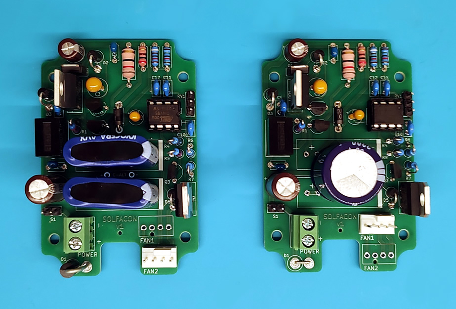
PCBs for two different configurations
Assembly of the PCB is straight forward, just solder the components onto the PCB at the designated locations. Mind component orientation, vertical/horizontal components, and seat components as close to the PCB surface as possible to ensure enclosure lid clearance.
- Bridge D1 using a staple jumper wire or similar.
- Bridge S1 using a staple jumper wire or similar.
- Ignore C-ALT - do not place components at this location.
- Ignore C7, C8, D4, R2, R3, Q2 - do not place components at these locations.
- Ignore C11, R4, R5, RV1, Q3 - do not place components at these locations.
- The fan header can be placed at either FAN1 or FAN2.
Final touches
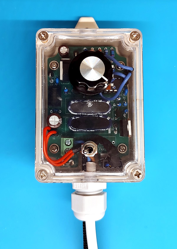
Enclosure with transparent lid
Screw the assembled PCB into the enclosure and mount the enclosure on the wall (optional).
Female MOLEX fan connectors can easily be taken apart (non destructively) such that they are easier to get though holes. On the back side of the female fan connector, there are small slots in the plastic through which metal clips can be seen. Using a needle or another pointy object, gently push down on the tiny clip and pull one wire out at the time. Run the wires through the hole in the enclosure and re-attach the plastic part of the connector. Be sure to attach the wires in the same positions.
Connect the wires for the solar panel to the POWER screw terminal, but do not connect the solar panel yet or do not expose it to light. Connect the potentiometer by connecting RV1 to RV1-A. Connect the on/off switch by connecting S1 to S1-A. Make sure that everything is connected correctly, and carefully place the lid on the enclosure. Connect the solar panel and let light hit the solar panel and the fans should spin up in a few seconds.